Reinforcing steel has to satisfy some basic requirements to efficiently perform in concrete structures. The durability of the reinforced concrete structures will greatly depend on the basic requirements. A few of them are as given below.
- Tensile strength
- Bond strength
- Ductility
- Bendability
- Weldability
- Fatigue strength
- Corrosion resistance
- Fire resistance
Tensile Strength
This is the most important requirement of steel reinforcement. With the development of high strength weldable steel (Fe 500 and Fe 550), a considerable economy has been achieved.
The advantages of using higher strength deformed bars are that they permit improved concrete placement by reducing reinforcement congestion. High strength steel implies high bond, and in turn, good quality concrete of appropriate matching strength is necessary around it. M-250 strength and above is desirable. Concrete should also be of uniformly high quality.
| Stress | Method | Method |
| – | Working Stress | Limit State |
| Tension | 275 N I/Sqmm | 500 N I/Sqmm |
| Compression | 190 N I/Sqmm | 335 N I/Sqmm |
| Shear | 230 N I/Sqmm | 415 N I/Sqmm |
| Bond | 40% more than that of plain bars | 60% more than that of plain bars |
There is a tendency or need to mix up reinforcement of different grades in the same member or in the structures in different members, such as columns, beams, and slabs. For example, the main reinforcement in columns can be of one grade whereas stirrups could be of another grade. This is in order as far as technical provisions for safe structural design are concerned. However, the electrochemical potential of reinforcement would vary from grade to grade of reinforcement and this can initiate corrosion. This particular factor is not yet fully understood and cannot be ignored. Durability provision has not only considered strengths but has also indicated the need for matching material properties. Therefore, there is a need to safeguard when two or more grades/types of reinforcement steels are used in one member.
Bond Strength
Reinforced concrete is a composite structure consisting of concrete of different grades and steel of different diameters and shapes and materials. The properties of reinforced concrete structures depend greatly on the bond between these two materials. The bond is due to the surface stresses transmitted between steel and concrete and is measured by the resistance to separate. This is called bond strength.
Reinforcement steel has two kinds of bonds in concrete. First is adhesion between steel and concrete. This bond is caused by the curing of the concrete surrounding bar. As the concrete gains strength, the bond increases between the steel and the concrete. Second is a mechanical bond which is achieved by lugs and helical ribs on the deformed bars or by hooks and kinks in the plain bars. The overlapping oblique lugs and the continuous helical longitudinal ribs provide a perfectly continuous bond.
If the lugs and ribs of the bars and their geometry are not proper it will adversely affect the handling, rebending, fatigue, and notch resistance. However, high strength deformed steel (TOR) bars available these days have much geometry for lugs and ribs, length, height, and width along with the shape and angle that it makes with the axis of the bar so as to get a maximum bond, balanced with Bendability, rebendability, fatigue as well as ensuring notch resistance which makes the reinforced steel workable on construction site.
The bond between concrete and steel is directly dependent on the deformations over the bars. Deformed bars/Tor steel develops a bond strength almost 3 to 4 times that of a plain rounded steel bar. At a slip of 0.1 mm, rounded bars provide an adhesive bond whereas high strength deformed bars or ribbed tor steel provide a shear bond. The surface profile of deformed steel bars satisfies the recommendations included in Indian Standards which give an excellent bond. In addition, the overlapping oblique lugs and the continuous helical longitudinal ribs provide a perfectly continuous bond.
It is not necessary that reinforcement must be in contact with each other for a required lap or bond lengths. The load transfer takes place through bond lengths via the surrounding concrete. The bonding of reinforcement at different locations even permits, appropriate bond length to transfer, the desired stress levels. These factors must be clearly understood as it avoids unnecessary kinking of the reinforcement steel.
Ductility
Ductility of reinforcement is an important criteria for the safe performance of a reinforced concrete structure, whereas control of carbon content is important for the ductility of steel. The elongation at rupture over a standard gauge length is called the ductility index. Although about 8% to 10% elongation over a gauge length of 5 times diameter is adequate enough, high strength deformed bars generally record about 17%.
Bendability
During the process of placing of reinforcement steel as per the detailed reinforcement layout given by the structural engineers, the reinforcing bars are required to be cranked, kinked, and/or bent. This requires the bar to be made up of bendable material. However, the Bendability of bars reduces due to the following factors. An increase in the yield point of steel causes decreases in its Bendability.
- The shear elements such as transverse ribs and lugs on the bar cause adverse notch effects and Bendability can reduce considerably. In case the ribs and lugs are filled uniformly and symmetrically during hot rolling, the longitudinal ribs are parallel and transverse lung are gradually merged into the core and do not cross the ribs, forming corners at the intersection which are stress raisers or stress concentration points.
- Sharp corners are formed between lugs or ribs and the core if any are smoothened due to plastic flow during twisting.
- Frost results in a considerable reduction of the Bendability and workability of reinforcing steel.
- As the diameter of the bar increases, Bendability decreases.
- If the diameter of the pin used for bending the bar is smaller than that specified, the bendability decreases and may render the bar useless.
Concrete is subjected to high compressive stress inside the bends of the reinforcing bars. This stress increases with the curvature or in other words, with the decrease in the diameter of the bending pin.
Excessive curvatures may also result in the crushing of the concrete within the bend. Due to this reason, the minimum diameter of the pin used for bending the reinforcing bars is specified.
Ribbed Torsteel can generally be bent through 180o around a pin having twice the diameter of the bar without any fracture or cracks. However, in actual application in the field, reinforcement bars are also often required to be straightened up after bending to correct the angle of the bend or to do other minor adjustments while being assembled. Experience has shown that even though the bar may withstand the bending it may not withstand reverse bending or straightening after bending.
Hence it is necessary to test the reinforcement steel for rebendability or reverse bending test. The compliance of this test ensures sufficient safety factors at the site. The requirements of the diameter of the mandrel or pin needed for bend and rebend tests. For grade Fe 415 high strength deformed bar, it is generally guaranteed that the bars will not break or exhibit cracks when bent through 45o about the pin or mandrel of specified diameter followed by ageing in boiling water for half an hour, and reverse bending through 22.5o.
The steel must not be bent on-site using a pin having a diameter less than the minimum specified for the rebend test. The bend and rebend tests are measures of the workability of a reinforcement bar.
Weldability
Welding mild steel rounds are generally done using mild steel electrodes and special welding techniques are not needed. The deformed bars particularly Fe 415 and Fe 500 are with softer chemical compositions, having carbon content around 0.20% and therefore, can be welded without needing special electrodes or special welding techniques. The bars in which carbon content exceeds 0.25% are generally unsuitable for welding.
The methods for welding deformed bars are recommended as follows:
- Electric arc weld (for bar diameter greater than 20 mm)
- Lap weld with longitudinal beads (for bar diameter 5 mm to 40 mm)
- Flash butt weld (for bar diameter 6 mm to 40 mm)
Oxyacetylene welding should not be used for welding deformed bars.
Electric Arc Welding: Electric arc weld with the chamfered joint can be made. The bar ends are beveled by a power saw or grinding tool before welding. The level faces must be smoothened using a hand file. The root run between the beveled faces should be of 2 mm to 3 mm and the sequence of runs can be as given in the figure. After four runs the bar is rotated by 1800 and the welding continued. When the last run is being done, the bar is rotated gradually by a full circle. The bar must be allowed to cool after each run before further welding.
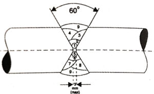
The diameter of the weld must be 1.2 times the bar diameter and the angle between the level faces should be maximum of 60 deg.
Lap Welding: The length of the longitudinal bead required to weld deformed bars is 10 times the diameter of the bar. Longer longitudinal beads should be divided into sections, each no longer than five times the diameter with a gap in between of the same length as that of the longitudinal bead. Symmetrical joints are preferred to asymmetrical joints especially when bar diameters are large. It is necessary to provide stirrups in locations where lap joints are done. It is preferable to reduce the spacing between the stirrups if lap joints are asymmetrical.
Flash Butt Weld: This method is used for all diameters but as it is costly and consumes a considerable amount of electric power it is not generally recommended for site work. It is more suitable for precast concrete industrial units. The capacity of the welding machine required must be minimum of 8 KVA per sq.cm of the bar cross-section and the pressure required must be 6kg/Sqcm.
Electrodes: Ordinary electrodes of mild steel grade with rutile coating are adequate. Electrodes with low hydrogen content will be more suitable. The size of the electrode recommended for various bar diameters and methods is given in the below table.
| Bar Diameter | 16 mm | 20 to 28 mm | 32 to 40 mm |
| Electric arc weld Root run (mm) Electric arc weld Other runs (mm) | – – | 2 to 2.5 3.0 | 2 to 2.5 3.0 |
| Lap welding (mm) | 3.0 | 3.5 | 5.0 |
Precautions and Design Consideration for Welding
The following precautions are required to be taken:
- Avoid overheating of bars.
- The electrode should not be lighted by touching the hot bar to avoid the notch effect.
- Slag, if produced after every run, must be chipped off and removed by brushing.
- The bar should be properly aligned and kept in the correct axis and it must be supported 1 m on either side of the joint.
- Untwisted ends should be cut off, if present at weld joints. A length of about 150 mm can be removed prior to welding.
- Bars should be cleaned and made rust-free at the joints which require welding.
The following design considerations are generally adopted.
- The design strength of weld joints of tension and compression bars shall be considered as 80% and 100% of the original bar respectively.
- Welds in curved or bend portion of the bars should be avoided. Welding should be done at least at a distance of 50 times the diameter of the bar from the bend or curved portion.
- Tension bars, if not under predominately fluctuating loads, can be welded in one section. However, if the fluctuating loads exceed 50% of the total load, then at the most only 33% of the bars at one section should be welded and for the rest of the bars, welding should be staggered.
- Whenever possible electric or flash butt welding is preferable for bars having a diameter of more than 18 mm. smaller diameter bars can be either butt or lap welded.
- When bars are required to be welded in situ or within the formwork or in case of connection joints of precast concrete elements in situ then lap welding is the only practical solution. Whenever lap joints of the bars are asymmetrically designed, an adequate number of stirrups and binders are to be provided in the weld locations.
Fatigue Strength
When a structural member is subjected to pulsating force it may fail at a stress lower than the yield strength of the material. This failure stress is termed as fatigue stress. The fatigue stress needs to be considered only in special cases when a very light structure is subjected to a relatively high repeated live load.
For reinforced concrete structures under repeated loading, where the stresses due to dead load are at least half the total stresses, fatigue needs not be considered in the design at all. The maximum repetitive stress that can be sustained by the material without failure for two million load cycles is generally accepted as a measure for fatigue stress. For roads designed as per IRC codes, no further reduction in stress is necessary to cater to fatigue failure.
Corrosion Resistance
Mild steel or high yield steel has to be protected against corrosion due to reaction with oxygen, moisture, and chlorides in the atmosphere groundwater, or sub-soil. The reinforcement steel bars are generally protected by providing concrete cover around them or by providing a protective coating on steel. The degree of this protection is greatly dependent on the following factors:
The grade of concrete used
- The higher the grade of concrete, the lower is the depth of carbonation, and hence, higher durability is obtained.
- Quality of cover and concrete in the cover portion.
- The main reason for the rusting of reinforcement is the poor quality of concrete around the reinforcement; this can be due to bad workmanship, poor compaction, and poor curing, etc.
Water to cement ratio (W/C) of the concrete mix
- Concrete with low W/C has a higher resistance to permeability of water, chlorides, and other harmful chemicals.
Thickness of cover
- Thicker the cover, the better the protection to the steel in concrete. However, beyond a certain thickness, there are good chances that the concrete in the cover are may crack or chip off, and hence, the thickness of the cover has to be restricted depending on location and loading on the structure.
Carbonation of concrete
- Concrete cover around the reinforcement steel offers passivation and prevents corrosion. However, over the years concrete alkalinity gradually reduces due to reaction with carbon dioxide and moisture in the environment. The pH value of fresh concrete is generally around 14. When the pH value reduces below 9.5, the passivation is reduced and corrosion commences.
Type of environmental exposure to concrete
- Concrete exposed to severe environmental conditions, such as fluctuating water table or subject to chloride or sulfate attacks, has to be properly designed considering the following factors:
- Types of cement
- Maximum W/C
- Minimum cement content.
Design Considerations
- Large width cracks in the tensile zone of concrete structures can damage the prospective concrete cover around the bar, and it is, therefore, essential, to restrict the crack width. Tests have shown that a crack width of 0.1 mm can withstand aggressive environmental attacks and no corrosion will take place if other aspects for concreting are properly taken care of. The maximum width of cracks in the structure should, therefore, not exceed 0.1 mm under service load conditions.
Use of rusted steel bars
- Little rust or brownish color on the steel bars is in fact not harmful. Loose mill scale and excess flaky rust not firmly adhering to the bars must be removed. Badly rusted bars if used in construction will not have a proper bond with concrete and will cause further rusting, resulting in oxidation of steel and the formation of ferrous oxide or hydroxide causing expansive stresses subsequently resulting in the spalling of concrete.
Fire Resistance
Failure of RCC structure subjected to fire can take place when the temperature of embedded reinforcing steel exceeds 500o to 600o C for a stand-up time of 66 to 73 min. At about this temperature proof strength of high yield deformed bars may reduce to 250 to 300 N/Sq.mm.
The tests have also shown that:
- Retention of strength at elevated temperatures appears to vary inversely with carbon content.
- The strength of twisted bars is more stable with the varying times of exposure.