Introduction
Tall building project brings together high strength material, experienced professionals, and innovations. Burj Khalifa which signifies human ambition to rise higher reflects an integration of these three critical aspects:
- High strength concrete till 601 m and 227 m steel spire at the top
- Collaboration among Architect, Structural Engineer, Wind Engineer, Building Facility Engineer, Façade Engineer, Geotech Engineer, and Construction.
- Innovation in concrete technology, lateral load resting system, and elevator.
Following key aspects of tall building projects:
- Design Stages
- Lateral Load Resisting Systems
- Strategies to Manage Wind Load
- Design Challenges
Design Stages
Design of Tall Building has following three stages
- Conceptual Design
- Preliminary Design
- Detailed Design
Conceptual Design
At this stage, Structural Engineer closely works with the Architect and Client representative to the understand objective of the tall building. This stage structural engineer works on a broad concept to transfer loads safely to the foundation, constructability, and economics.
Following engineering disciplines working together on challenges, alternative viable solutions, and inter-discipline impact.
- Tall Building Project
- Architect
- Structural Engineer
- Facade Engineer
- Wind Specialists
- Geotechnical Specialists
- Fire Consultant
- Lift Specialists
- Construction Advisor
The key decision freezes at this stage are
- Orientation and External form of Building to ensure minimum wind loads
- Floor System
- Lateral load resisting system
- Constructability
- Approximate cost of construction
A structural engineer presents two alternative viable solutions along with sketches to describe the load path and construction sequence. Structural engineer collaborates with Architect, Geotechnical Engineer, Wind Engineering Firms, MEP (Mechanical, Electrical, and Piping) and Construction experts to capture all critical input in the conceptual the tall building as a single giant cantilever beam to arrive stiffness requirement for lateral load resisting system Architectural drawings are submitted to planning/local authority for initial approval along with Conceptual design report.
Preliminary Design
The second stage of the tall building project. The key objective of this stage is to generate drawings and quantity estimates for the tendering process.
At this stage, a detailed 3D Computer analysis model is generated in leading software ETABS, SAP2000.
Geotech investigation agency is appointed to carry out soil exploration at the site. Geotech consultant recommends the type of foundation, allowable bearing capacity, and stiffness for the Soil-Structure interaction model.
Wind Consultant is appointed to perform wind tunnel study and recommend modification for sustainable design.
A typical wind-tunnel test to evaluate structural loading on a building consists of the following steps:
- Simulate the natural wind environment in the tunnel, including profiles of mean speed and turbulence, including both the far-field and near field.
- Construct a model geometrically scaled to the building, place it in the simulated environment, and “observe” what happens using appropriate instrumentation.
- Obtain the initial dynamic characteristics of the building from the structural engineer.
- Define the site wind climatology & assign design wind speeds.
- Analyze and interpret the observed results, in view of design speeds and structural dynamic properties, to obtain static-equivalent loads and accelerations.
- Interact with the structural engineer to refine or optimize the structure.
The test provides wind load at each floor level for along wind load, across wind loading and torsional moment. Following three tests Wind tunnel test method.
| High Frequency Force Balance Test | High Frequency Pressure Integration | Aerodynamic Elastic Model Test | |
| Purpose | Estimation of wind load distribution along height capturing primary models of vibration | Design of HVAC and Cladding Pressure capturing Primary and Higher modes of Vibration. Accurate evaluation of wind load | User comfort at top floors for acceleration criteria |
| Duration | Quick Turn around | A Longer duration | |
| Input | 3D computer analysis model, Form of Building | 3D computer analysis model, Form of Building | 3D computer analysis model, Form of Building |
Aspect Ratio
The overall slenderness of a tall building is usually defined by its aspect ratio also called the “Height to the base ratio” which is the height of the building divided by its narrowest plan dimension. Preferably the value of aspect ratio is less than 7. The aspect ratio of the world’s second-tallest building “Shanghai Tower” with height 632m is 7. Tall buildings with aspect ratio above 8.
Lateral Load Resisting System
The lateral load resisting structure also referred to as the lateral stability system consists of all structural elements which form part of the load path for transmitting the lateral effects of all loads (wind, earthquake, eccentric gravity effects, and unbalanced lateral earth pressure load) from their sources to the foundation. These elements typically include walls, vertical truss, beams, columns, and floor diaphragms.
The effects of wind on lateral load resisting structure can be considered in two parts, namely:
- ULS load effects affecting the strength design of lateral load resisting structure;
- Wind motions due to dynamic response to SLS wind loads affecting the serviceability of the structure in terms of human perception.
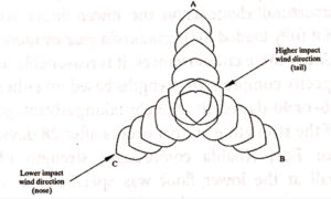
The general principle behind the efficient design of the lateral load resisting structure of tall buildings is to engage the perimeter structure with the core within the constraints of planning and architecture. By effectively engaging the perimeter gravity columns the structural width of the lateral load resisting structure is increased dramatically. Also as the perimeter columns are preloaded in compression due to gravity loads, they can resist wind-induced tensions very economically. Adjacent cores are often engaged together with “header beams” allowing the core boxes to act in a compound manner in resisting the lateral loads. i.e. to a develop “push-pull” couple over their cross-sections rather than simply bending independently. The perimeter columns can be engaged with the core by either direct or indirect “shear linkage” elements. The direct shear links can be provided by outrigger walls connecting the core and the columns. The indirect shear links can be provided by belt walls, offset outriggers. The figure shows the direction of lower impact wind direction which is along with one of the noses. Both this information was integrated to orient tower resulting in the most economical design.
Lateral Load Resisting System and Representative Building Example
| Structural System | Name of Building | Height of Building | No of Floors (Above/Below Ground) | Year of finish | Material of Construction | Slenderness (Height to Width Ratio) | Gross Floor Area (m2) |
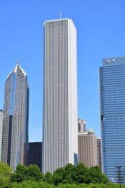
| Framed Tube | Aon Center | 346 | 83/5 | 1973 | Steel | 5.85:1 | 334,448 |
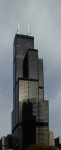
| Bundled Tube | Wills Tower (Sears Tower) | 442.1 | 108/3 | 1974 | Steel | 7.45:1 | 416,000 |
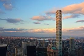
| Tube in Tube | 432 Park Avenue | 425 | 85 | 2015 | Concrete | 15:1 | 65,497 |
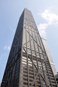
| Trussed Tube | John Hancock Center | 344 | 100 | 1969 | Steel, Composite floor | 6.84:1 | 260,126 |
| Core + Outrigger | Taipei 101 | 508 | 101/5 | 2004 | Composite Concrete | 6.8:1 | 198,347 |
| Buttressed Tube | Burj Khalifa | 828 m / 606 m (concrete) + 222 (steel) | 163/1 | 2010 | Concrete | 309,473 |

Strategies to manage wind
The tall building design is governed by wind loading. The following strategies are used to manage wind loading in a tall building in Dubai prevailing extreme wind direction is North-West. This can be observed in the Google map for Dubai Airport runway orientation. The direction of lower impact wind direction which is along with one of the noses. Both this information was integrated to orient tower resulting in the most economical design.
| Strategy | Example Building |
| Corner cut and corner recession (5 to 10% Building width | Taipei 101 |
| Tapering along height | Petronas Tower |
| Setbacks along height | Sears Tower |
| Orientation | Burj Khalifa |
| Twisting | Shanghai Tower |
| Corner chamfered | World Trade Center |
| Elliptical shape in plan | Al Mas Tower, Dubai Guangzhou International Finance Center, China |
Tall Building Challenges
The demonstrates challenges faced by structural engineer in tall building projects.
- Structural lateral strength and stiffness
- Differential axial shortening
- Motion (acceleration) perceptions at higher levels
- Setting out and Vertically
- Wind loading
- Hoisting of Materials
Concrete for Tall Building
Traditionally, compressive strength tests are made at 28 days, but many high-rise buildings now requiring high strength concrete employ a construction schedule whereby the structural elements in the lower floors are not fully loaded for periods of a year or more. Under these circumstances, it is reasonable to specify the compressive strengths of concrete based on either 56 days or 90 days of compression test results, thereby taking advantage of the strength gain that occurs after 28 days. For Burj Khalifa compressive strength of wall at the lower floor were specified Cube compressive strength 80 MPa and Young’s modulus 43,800 Mpa at 90 days.
Concrete provides the following advantages in the tall buildings.
- The mass and rigidity of concrete provide twice the dampening effect compared to steel, reducing forces on the super-tall building due to wind and the cost of construction.
- Structural concrete is naturally fired resistance and sound insulation.
- Advancement in concrete pumping technology, including the introduction of placing booms, fast delivery of concrete possible, make easy, freeing tower cranes for other work.
- Improvements in concrete mixes, including strength & modulus of elasticity, have made high-rise construction more attractive. Self-consolidating concrete is increasing in use too.
Approximate concrete consumed in the tall building can be arrived using formula recommended by Dar’s formula
Volume of Concrete in m3/m2 Gross Floor Area (GFA) = (0.62N+15) m3/m2 to (0.62N+60) m3/m2
For 80 Storied Tower with total Gross Floor Area 130,000 m2, Concrete volume will be in the range of
Vmax= (0.62×80+60) x 130,000 = 14.248 Million m3 to
Vmin= (0.62×80+15) x 130,000 = 8.398 Million m3
Conclusion
The pillar for completion of the tall building project is integrated collaboration among multi-discipline. Tall building Design involves broadly three stages, Concept Design, Preliminary Design, and Detail Design. An idealized 2D beam model of the building will give sufficient results for the preliminary design. An increase in height of the building provides an opportunity to innovate new Lateral Load Resisting Systems (LLRS). The lateral load resisting system which is most viable for 300 m tall towers does not suffice for the 600 m tall tower. Using various strategies to manage wind load on the tall buildings may reduce overturning moments at the base by around 25% on tall buildings giving overall cost savings. Inherent mass, damping, durability, and fire resistance of structural concrete makes it the most suitable material for the Tall Buildings.