Cracks might be big or small, structural or non-structural. All of them can be a nuisance by way of either marring the appearance or function as a passage for atmospheric polluting gases or moisture to enter the body of concrete and cause distress.
Cracks in the concrete structure do not always mean that the structure is not useable. As cracking of concrete is inherent or innate, what really matters is the type of structure & the nature of cracking. Cracks that are acceptable for building structures or building construction may not be acceptable for water retaining structures. Considering that cracking can never be eliminated, it is necessary to be aware of the causes, evaluation, and methods of repair whatever is required.
Cracks are generally of two types:
- Structural Cracks
- Non-structural
Cracks can take place in hardened or unhardened concrete.
Structural Cracks
Hardened reinforced concrete cracks in the tensile zone when subjected to externally impose or apply structural loads. These cracks can be limited to acceptable structural integrity and aesthetics levels by utilizing the appropriate design and detailing techniques.
Non-Structural Cracks
Concrete is also liable to crack in the plastic state & hardened state because of stress which it intrinsically sustains because of the nature of its constituent materials. These intrinsic cracks are as inescapable as structural cracks. It is often possible to predict when intrinsic cracks are likely and limit them to acceptable levels through good design and/or proper construction techniques.
Dormant and Live Cracks
Cracks caused by shrinkage, temperature gradient due to hydration, and alkali-silica reaction (ASR) are less dangerous than cracks caused by thermal expansion and loads. This is because shrinkage and hydration temperature gradient results in dormant cracks and other mechanisms result in live cracks (where the width increases with time).
Dormant cracks, particularly narrow ones, are more likely to undergo autogenously healing & realkalisation. The crack may heal owing to the following conditions:
- Carbon dioxide (CO2) diffusing into the crack leading to carbonation of the calcium hydroxide and precipitation of calcium carbonate.
- Cement hydration due to presence of moisture.
- Hydroxide diffusing from the bulk concrete into the healed zone thereby increasing the pH in that area.
Live cracks are more likely than dormant ones. They result in the collection of debris at the base owing to the movement of the sides of the cracks. However, autogenous healing is unlikely with live cracks.
Causes of Cracking
Cracking will take place whenever the applied strain exceeds the tensile strain capacity of the concrete. The tensile strain capacity of concrete varies with age & with the rate of application of strain.
Cracks can appear at any time. The age at which some typical cracks can occur is given in the below table.
| Sr. No. | Types of Cracks | Age |
| 1 | Plastic shrinkage cracks | First few minutes or hours after concreting. |
| 2 | Plastic settlement cracks | First few minutes or hours after concreting. |
| 3 | Because of corrosion | After one year or many years. |
| 4 | Due to loads | After loads are imposed & the time duration of loading. |
| 5 | Due to dead weight | Just after formwork supports are removed. |
| 6 | Due to chemical changes in hardened concrete. | After one or many years depending on the chemical attack from outside or chemical reaction from within. |
Critical Cracks Width
The most common reasons for controlling cracks widths are following:
Appearance: Unsightly cracking should be avoided since it may cause concern to the occupants of the structure. It may also contribute to unsightly staining on exposed external surfaces, where slats and rust are washed out from the crack.
Durability: Excessively wide cracks might lead to corrosion of the steel reinforcement which in turn may lead to spalling of concrete because of the expansive nature of the corrosion process.
Water-tightness: This is of significance in water retaining structures.
In particular instances, there might be different reasons for controlling cracking in addition to the three reasons cited above.
Crack width is, generally, to be taken to mean the measurable width of a crack at the surface of the concrete. Crack width limitation is important from durability consideration. Most structural codes recommend maximum allowed crack widths.
Codes generally consider cracking caused by externally imposed conditions like live loading & give a formula for calculating the crack width in the design phase. Mainly bending and tension or bending and axial loads are considered. The direction of such cracks is perpendicular to the direction of main steel reinforcement. Plastic shrinkage cracks follow the line of steel reinforcement.
According to IS:456-2000, the surface width of the cracks should not, in general, exceed 0.3mm in members where cracking is not harmful and does not have any serious effect either on the durability of the structures or on the preservation of reinforcing steel.
In members, where cracking of the tensile zone is harmful either because they are exposed to the effect of weather or constantly exposed to moisture or in contact with groundwater or soil, an upper limit of 0.2mm is suggested.
For aggressive conditions, the surface width of cracks shouldn’t surpass 0.1mm. The crack width is measured at the surface for the above purposes or objectives. However, some other codes specify the width at points near the reinforcement.
Crack width from point of view of aesthetics:
Cracks are acceptable provided they are not noticeable to a casual observer. The width and length of crack which will satisfy this criterion are obviously not constant. This will depend upon how close the casual observer can get to the member in question. It will also depend on the surface treatment of concrete, lighting conditions, whether the concrete is in a wet or dry state and the angle of viewing.
A diagram, indicating acceptable crack width relating to the importance of the structure and the viewing distance, provides a suitable guide.
Control of Cracking
A precondition for the formation of controlled cracks
The important condition is that all sections of a member which are likely to crack should be able to carry the applied loads both before and after cracking without excessive deformations.
In general, this requires that a certain minimum amount of reinforcement is present in the section. If there is too little reinforcement, or it is in the wrong place, then it will yield when the first crack forms, and no other cracks will form thereafter.
The minimum steel area can easily be calculated for pure tension on the condition that the steel within the section should be at least as strong as the concrete, thus:
As fy ≥ Ac ft or P ≥ ft/fy
Where,
As = steel area
fy = tensile strength of steel
Ac = concrete area
ft = tensile strength of concrete
P = reinforcement ratio
The figure for flexure will be substantially lower since only part of the section is subject to tension. Besides this overall condition, there is also a local one. Each bar, considered separately, must be capable of carrying the load from the surrounding concrete on cracking.
Parameters that affect crack widths
Consideration can be given to three major parameters which influence the crack width.
The first of these is the tensile strain at the point of consideration. This defines the extension that has to be absorbed by crack. Not surprisingly, crack widths are found to be proportional to tensile strain. This tensile strain may result from the applied loads, shrinkage, and restrained temperature movement, and/or any combination of these.
The second is the proximity of longitudinal bars from the point of consideration on the section. The closer the bar is to this point, the smaller will be the width. This means that closely spaced bars, or bars with small concrete covers, will give a narrower crack than widely spaced bars, or bars with large concrete covers.
The third controlling parameter is the depth of the tension zone. The effect of the depth of the tension zone is important in slabs and prestressed beams but is much less significant in deeper reinforced members.
Measurement of Crack Width
The common methods use graduated magnifying glasses, templates, and filler gauges. There can be an accurate measurement for a wide range, but when two people measure the width of a crack of the order of 0.1mm to 0.2mm, it is unlikely that they will obtain similar or repeatable results. This is simply because cracks are not simply parallel-sided gaps.
The nature of cracks is such that while their width is measured at the concrete surface, they may be wider in the interior.
Some cracks –
- Taper quickly from the surface
- Remain approximately parallel throughout the section
- Widen within the section
Today we refer to cracks by their width measured at the surface, there being no other way to measure crack width other than at its surface.
Micro-cracks can result from drying shrinkage, thermal shrinkage, or externally applied loads. These cracks are larger than most capillary cavities and generally provide continuous flow paths throughout the cement matrix.
What exactly is a micro-crack? The term “micro-crack” is frequently used, rather uncritically, although some definitions have been suggested. Slate and Hover (in their book on Fracture Mechanics of Concrete) defined micro-cracks as having a width of fewer than 100 microns, while still being detectable. Jensen defines micro-cracks as extended faults with a width of fewer than 10 microns, which facilitate fast transport of fluids or gases through the concrete.
Based on these, Kjellsen and Jennings also proposed the same definition of micro-cracks, which was considered as reasonable physical interpretations of micro-cracks. Their upper limit was set at 10 microns; the lower limit was defined as a separation resulting from overstepping the local strain capacity, such that there is no “stress” transferred across the crack. This implies the lower limit could be on a manometer scale and probably not detected by any other commonly adopted methods for studying micro-cracks.
Early Thermal Movement and Cracking of Concrete
As the heat of hydration is dissipated the concrete cools and shrinks. If a reinforced concrete member is not restrained externally, then the stresses induced in both the concrete and steel due to differential thermal contraction are small. It is only if the member, or part of the member, is restrained that substantial cracking can occur. The actual form of the external restraint has a fundamental influence on the cracking behavior. Three important forms of cracking in immature concrete are as follows:
- Direct tension in a thin wall or slab with end restraint.
- Direct tension in a thick wall or slab with end restraint.
- Warping in a wall with significant base restraint.
Reduction of the Total Thermal Contraction
The thermal contraction of the immature concrete depends on the temperature fall from the hydration peak to ambient. The peak hydration temperature is affected by both the rate of heat liberation and the rate of heat dissipation.
Cracks Control
All three forms of cracking give rise to tension cracks. Hence in the simplest case direct tension, in a thin wall or slab with end restraint only, is considered first. It can also provide the basis for controlling cracking due to the other forms of restraint.
In general, it is uneconomical to attempt to reduce the thermal contraction to a level that enables the concrete to remain uncracked along long lengths of wall or slab which do not contain movement joints. If cracks are going to occur, then it is essential to control the widening of the cracks in some way and the most convenient solution is to use distribution reinforcement. The design of such reinforcement involves two distinct concepts. First, the distribution reinforcement must be stronger than the immature concrete, otherwise, the first crack which forms will continue to widen with the yielding of the reinforcement. Second, the actual width of fully developed cracks must not be excessive concerning the required function or exposure conditions of the structural member.
Critical Steel Ratio
If the reinforcement is to be stronger than the immature concrete i.e. if the steel is to be capable of not yielding at a construction joint or similar position of weakness, then reinforcement not less than the critical steel ratio rcrit must be provided as follows:
rcrit = ut/fyt
Where,
ut = tensile strength of immature concrete at 3 days
fyt = characteristic yield strength of reinforcement
ut may be taken, very approximately as equal to (uk/20)2/3 N/mm2
where uk = characteristic cube strength at 28 days.
Crack Spacing
The crack spacing s, depends essentially upon the ratio of the tensile strength of the immature concrete cross-section and the bond strength between all the reinforcement and the immature concrete, i.e. s is given by
ut db/fbu 2r’ ≥ s ≥ ut db/fbu 4r’
When
db = diameter of reinforcing bars
fbu = average bond strength between immature concrete and reinforcement
r’ = steel ratio based on the gross concrete section
The ratio ut/fb may be taken as unity, 4/5 and 2/3 for plain round, medium-bond, and high-bond bars respectively.
Crack Width
If the shrinkage strain is assumed to be accommodated by the elastic expansion of the concrete then the maximum crack width, Wmax is given by the thermal contraction and the maximum crack spacing Smax.
Wmax = Smax (T1 + T2) ∞c
Where,
T1 = fall in temperature from the hydration peak
T2 = fall in ambient temperature due to seasonal variations
∞c = effective coefficient of expansion of the concrete
The value of T1 should be taken as not less than 30oC and 10oC for summer (initial concrete temperature of 20oC and timber shutters) and winter (initial concrete temperature less than 10oC and steel shutters)
Respectively, T1 should be increased if the cement content exceeds 400 kg/m2, wall thickness exceeds 300mm, or rapid hardening Portland cement is used.
When considering the seasonal temperature variation, additional cracking can even occur in matured concrete; hence µc may be taken, for convenience, to be the same as for immature concrete. Crack widths should generally not exceed the following values:
0.4mm – All members requiring structural stiffness
0.3mm – General concrete members
0.2mm – Concrete members exposed to climatic conditions
0.15mm – Water retaining members with almost continuous contact with liquid
0.1mm – Severe exposure, e.g. alternate wetting and drying
Types of Cracks
General Cracks
Cracks occur in concrete in two physical states. One is when concrete is in prehardening (plastic) stage and the second is when concrete is in the hardened stage.
Structural Cracks
The structural cracks of different types are illustrated below figures along with their important characteristics and possible reasons.
Flexure Cracks
| Member | Crack Type | Important Characteristics | Possible Reasons |
| R C Beam | Flexure | Originates in maximum moment region. May be single or in groups. Maximum width at bottom/top of the beam. | The flexure capacity of the beam is inadequate or insufficient. Cross-section or main reinforcement insufficient. |

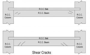
Shear Cracks
| Member | Crack Type | Important Characteristics | Possible Reasons |
| R C Beam | Shear | Originates nearer to supports. May be single or in groups. Maximum width at neutral axis region or bottom of the beam. | The sheer capacity of the beam is inadequate. Cross-section or torsional reinforcement is insufficient. |
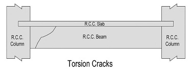
Torsion Cracks
| Member | Crack Type | Important Characteristics | Possible Reasons |
| R C Beam | Torsion | Originates nearer to maximum torsion region. Single, generally uniform width. A torsion crack takes place over the whole periphery in helical form. | The torsional strength of the beam is inadequate. Cross-section or torsional reinforcement is insufficient. |
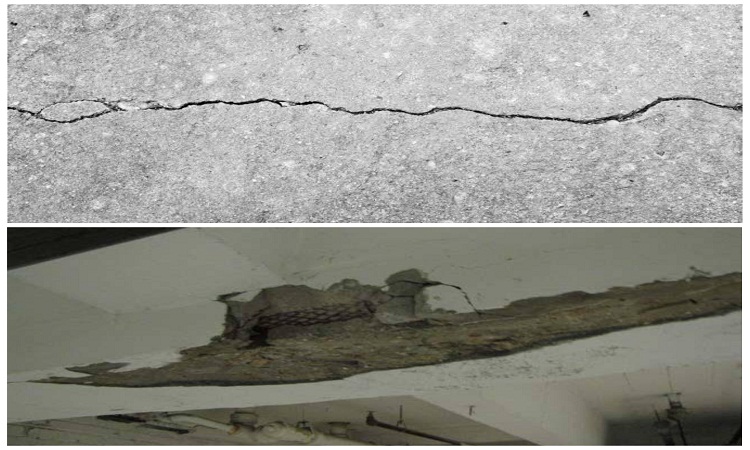
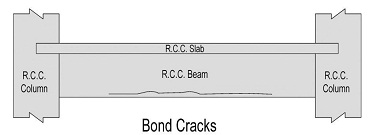
Bond Cracks
| Member | Crack Type | Important Characteristics | Possible Reasons |
| R C Beam | Bond (corrosion) | Runs above the line of reinforcement. Uniform width in general. | The bond between reinforcing bars and concrete is not satisfactory, maybe because of corrosion of bars or fire damage. |
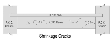
Shrinkage Cracks
| Member | Crack Type | Important Characteristics | Possible Reasons |
| R C Beam | Shrinkage | No regular pattern or thickness and in general. Superficial. | Curing is inadequate or has no control over the water-cement ratio. Usage of the excessively rich mix. Shrinkage reinforcement, if any, is insufficient. |
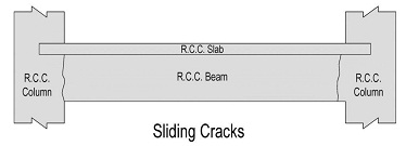
Sliding Cracks
| Member | Crack Type | Important Characteristics | Possible Reasons |
| R C Beam | Sliding | Runs vertically at the edge of supports. Maximum width at bottom of the beam. | Concrete in the beam is disturbed at an early age when adequate strength is not realized. Maybe because of disturbance of formwork at the green stage or early deshuttering. |
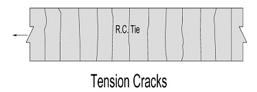
Tension Cracks
| Member | Crack Type | Important Characteristics | Possible Reasons |
| R C Tie | Tension | Appear over the whole periphery. Normally over the whole length of the structural member. Parallel to each other. Uniformly observed. | The capacity of the member in tension is inadequate. Tensile reinforcement is insufficient. |
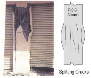
Cracks in Columns
| Member | Crack Type | Important Characteristics | Possible Reasons |
| R C Column | Splitting | Building in that region. Short parallel vertical cracks. Varying widths. | Inferior quality concrete. The load-carrying capacity of the column is inadequate. Cross-section or reinforcement is insufficient. |
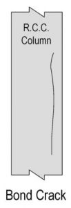
| R C Column | Bond (corrosion) | Runs above the line of reinforcement. Uniform width in general. | The bond between reinforcing bars and concrete is not satisfactory. Maybe because of corrosion of bars or fire damage. |
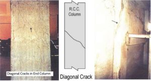
Cracks in Columns
| Member | Crack Type | Important Characteristics | Possible Reasons |
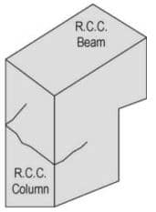
| R C Column | Diagonal | Runs diagonally across the section. Can occur anywhere in the height. Uniform thickness. | The load-carrying capacity of the column is inadequate. Cross-section or main reinforcement insufficient. |
| R C Column | Horizontal | Occurs near the beam-column junction. | Moment resistance capacity of column inadequate or deficient in the corresponding region. Inadequate quantum of reinforcement or disposition of reinforcement not satisfactory or acceptable. |