Introduction
A new place of pilgrimage, tourist attraction, and architectural and engineering marvel was created on the hills of Kalkaji, New Delhi, in December 1986. This beacon is the mother temple of the Baha’i faith in the Indian Sub-continent.
This temple is a symbol manifesting the Baha’i faith revealing the simplicity, clarity, and freshness of this new revelation, in distinction to the beliefs and symbolism of the many sects. In showing respect for the basic beliefs of the old religion, this new temple has also played the role of reminder for every faith that all the religions of God are one and that the Baha’i faith, for all that it may have many new features, is in no way cut off or detached from the life of the Indian people but rather looks upon them with all respect & faith. The temple design is unique in the sense that it has not imitated any of the existing Indian architectural schools, but at the same time, the architectural shape of the temple is very familiar to the Indian people and their religions.
To the Indian ethos, the lotus has been the fairest flower probably the most perfect flower in the world, symmetrical, exquisitely beautiful, and sacred too. From the earliest times to this day, this flower is popular throughout the length and breadth of India. In the monuments of Hinduism, Buddhism, and Jainism, Lotus motifs are depicted.
The Lotus symbol can be easily traced in Zoroastrianism, the oldest religion’s, architecture. The lotus flower is one of the oldest and most beautiful elements used in the patterns of Persian carpets. Lotus finds a place in Islamic architecture too. For example, the shape of a lotus occurs in the design of the perforated plaster works in the mihrab (prayer nitch) of the Malil mosque in Kirman.
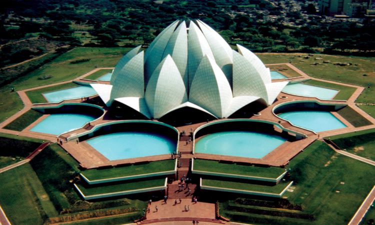
The Baha’i faith is said to embody nine major faiths of the world. The architect Mr. Fariburz Sahba, after extensive travel in India, conceived the Baha’i Temple not as an abstraction of the lotus but literally in the shape of a just opening lotus bud. To symbolize the nine major faiths which are embodied in the Baha’i religion, each component of the temple is repeated nine times. With entrance leaves, outer leaves, and interior leaves each nine in number, this Lotus temple has a roof containing 27 petals and an interior traced dome. All petals springing from a podium and surrounded by pools, house the main assembly hall.
It is said by Dr. Karan Singh, Scholar, Educationist, and a Great Public Figure in India. “The Baha’i house of worship will surely be one of the marvels of world architecture. The concept of Lotus, a divine symbol in many of the great religions including Hinduism, provides the basis of this unique structure”. “Fragile flower enshrining an idea, the idea of light and growth of shelter of petals interposed between earth and sky” is how the Baha’is perceive their temple in India.
It is said by Mrs. Mahvash Rowhani, Secretary of State Baha’i Council, “The Baha’i house of worship is not only a place where people go to pray and worship. The main aim of this house of worship, besides being a silent teacher is to bring together the hearts of men and establish world peace and unity. This house of worship will in the future serve the people. There will be various institutions serving in different fields like Research Centre, Home for the aged, orphanage, etc.”
Baha’i Temple Abroad
Baha’s temples have been constructed all over the world. Most of them are Architectural marvels. There are temples in the US, Uganda, Germany, Australia, Panama, and Samoa. The Baha’i Temple in Illinois, Chicago, US, took 40 years to build and was completed in 1952. It is still considered by many to be the most beautiful concrete structure in the world. This temple is an example of exceedingly beautiful ornamental architecture that has been created in concrete. It is called the temple of lights due to the brilliance it exhibits, in sunlight or moonlight, like a shimmering jewel.
The concrete mix was specially designed to give form finish white color with white quartz aggregates on the concrete surface reflecting the light rays falling on the structure. Special care was taken so that the concrete surface remains white. White cement and white quartz aggregates were used in concrete to make it resemble a marble finish. The exquisitely sculpted ornamentation was achieved by properly designing the concrete formwork for both precasts as well as for in-situ elements. This 51 m high structure was created by John. J. Earley and designed by Architect Louis Bourgeois. This nine-sided temple has a dome roof that measures 27 m in diameter.
It was, therefore, a challenging task for Architect Fariborz Sahba to design a structure in India that is eye-catching in beauty, symbolic in nature, and an architectural marvel. It also posed a challenge to the Engineers involved in its design and construction as odd-shaped structures are extremely difficult to design and construct. Such structures have also posed durability problems in the past, the living examples being the Sydney Opera and the above referred Baha’i temple.
General Arrangement
The Temple complex is located in a spacious plot of 26 acres of land on the hills of Kalkaji.
Main House of Worship
Lotus-shaped superstructure houses the temple proper (assembly area) while the basement accommodates electrical services and plumbing services.
All the bridges around the lotus are walkways with beautifully curved balustrades.
Bridges and stairs surround nine pools representing the floating leaf of the lotus. Nine pools surround the temple structure.
The podium all-round the basement surmounting it is supported on a system of curved beams. Three groups of nine shells spring from the podium and form a ring of nine arches. The entrance and outer leaves are interconnected. Inner leaves spring from the arches to a height of 33.6 m being jointed at a high level by a system of radial beams supporting the plant room. The Interior dome comprises fifty-four ribs with shells between, also rising from the arches.
In short, as seen from the outside the lotus structure has three groups of petals. Some petals open outward, some inwards, and some are partly closed. Inside three groups of petals is the interior dome.
Ancillary block
It houses the reception center, library, administration, and toilet blocks.
Geometry
Spatial forms for the shells following the concepts and constructible were developed with the aid of computers capable of providing any views and necessary geometric information. The final accepted solution is that entrance and outer leaves would have spherical surfaces and inner leaves would be formed from toroidal surfaces. Arch soffits were to lie on parabolic conoids. The interior dome was developed from nine interesting spheres, eighteen of the ribs spanning between points on the arches and lying on the surface of base spheres. From each of the thirty-six interactions, a circular rib springs upwards and supports the hub to the radial beams between the inner leaves.
Entrance Leaves and Outer Leaves
The shell is uniformly 135 mm thick towards the bottom and increases to 255 mm up to the top beyond glazing. The outer leaf has a 15.4 m width and rises up to 22.5 m above the podium level.
Inner Leaves
The inner leaves rise to an elevation of 34.3 m above the inner or internal podium. The inner leaves are uniformly 200 mm thick and have 14 m as maximum width.
Arches
The nine arches which almost bear an entire load of the superstructure are placed at angular intervals of 40°.
Environmental Control
Freshness is one of the objectives of the concept. Delhi is hot for many months in a year with varying degrees of humidity. Air conditioning on the temple premises was ruled out on account of the prohibitive cost of installation and maintenance.
Constant draught of cool air passing over the pools and through the basement flows into the hall and out through the openings at the top. This ventilation is complemented in two different ways. A set of exhaust fans are planned in the dome to cool the concrete shell & prevent transference of heat into the temple while the second set of fans funnel air from the auditorium into the cold basement where it is cooled & recycled back into the auditorium. This system and its maintenance is by far a cost-effective solution to air-conditioning. It has resulted in pleasant and agreeable temperatures inside the temple.
Lighting
The entire superstructure is designed to function as a skylight. The interior dome is spherical & patterned after the innermost section of the lotus flower, light enters the hall in the same way as light passes through the inner folds of lotus petals. Light filters through these inner folds of the lotus structure and are diffused throughout the hall. The central bud is held by 9 open petals, each of which functions as a skylight. The 9 entrance petals complete the design. The external illumination is arranged in such a way as to create the impression that the lotus structure is afloat upon the water by having the light focused brightly on the upper edge of the petals.
Land Scaping
Nine pools around the building form the principal landscaping. At the same time, they display the green leaves of the lotus afloat on water. Moreover, the pools and the fountain help to cool the air that passes over them and then into the hall. The entire 26 acres of land have been beautifully treated with appropriate landscaping.
Design Basis
Generally, Indian standards have been adopted in the design of this complex including seismic loading. Wind speeds were taken as those having 500 years return period, projected from the date recorded by the Delhi Meteorological Office, and formed the basis for wind load workout. A wind tunnel test on a model to a scale of 1:125 was conducted at the Aeronautical Engineering Department at Imperial College London. Wind pressure distribution on the structure and glazing were derived in the test. The model test was also used to indicate natural ventilation characteristics using smoke plumes.
Temporary Works
Several mockups were constructed to check the feasibility of the methodology and sequence of construction. Geometric form, the practicability of fixing the complex reinforcement, and the method of concreting technique were also examined. Prototypes of arch/column junctions, entrance and inner leaves, and interior dome elements were made in this way. The experience gained in these exercises helped, to a great extent, in the construction of high-standard structures meeting the correct shapes and finishes envisaged.
Staging and Formwork
In the design of formwork, the deflection was limited to 3 mm over a distance of 1 m (including errors in fabrication and erection). The important aspects considered to arrive at the general arrangement of the staging supporting the inner leaf and interior dome formwork are:
- The concreting of the shells should be taken up 3 at a time, 120 deg. apart, so that the lateral loads on the staging supporting the formwork were as far as possible reduced.
- Construction joints were as far as possible to be avoided so that the exposed concrete surface does not show any lines other than the architectural pattern. For the internal leaf of lotus, construction joints were to be located above 24.8 m level so that they are not visible from the floor level. All other shells were proposed to be cast in a single continuous pour.
- The staging should support the radial and base ribs without interference with the structural steel members. After de-shuttering, the inner leaf, the structure should be able to support the formwork of inner layers of shells of the interior dome with minimum modification.
With all the above considerations, a space frame consisting of 9 radial cusp frames & 9 re-entrant frames with circumferential & diagonal members closely following, the profile of ribs and shells were considered most suggestible.
For steel staging, a structural steel framework with welded joints was considered to be most suitable because deflections due to slippage of joints could be avoided and fabrication is also easier.
The inner surface of all the shells was to have uniform bush hammered exposed concrete surface with architectural patterns. For the inner leaves, these patterns were formed out of radial and vertical planes intersecting the surface of tours. For the outer and entrance leaves, as also the interior dome, the patterns were formed out of longitudes of spheres.
Full-scale mockups bottom surface of each of the shells were first made at ground level and architectural patterns were marked on this surface. The frame of each form panel was fabricated according to calculated dimensions and cross-checked with the measurements from the mock-up.
Great care had to be taken while carrying out fabrication and erection of about 2 lakhs square feet (18605 m2). 260 tons of steel was used for the temporary support of the super-structure. Even the temporary steel structure had to be given a proper curvature to match the required geometry.
Inspection
Accuracy of shuttering and proper placing of reinforcement was an essential and primary requirement for this job. lnspite of several checks from time to time, final checking of reinforcement at night just before concreting was also carried out as a quality assurance measure.
Foundation
Since this temple complex is a monumental place with high durability, the risk-free foundation was a must. The complex site was underlain by heavily fishered quartzite. Lenses of mica were also present at random. Hence, all column foundations were designed as mass concrete pads or reinforced concrete pads. Foundations were designed for full seismic forces and moments. The excavation commenced in April 1980. Nearly 2,12,000 cubic feet of rock were excavated manually.
Superstructure
After a lot of deliberations cast-in-situ concreting for the entire superstructure and also the basement had resorted.
Sequence of Construction
The basement and inner podium were constructed first. It was observed that during the 19-week-long concreting of podium concrete, each worker must have carried 7500 Kg of concrete in a 25 kg head load and walked nearly 21 km in a day. All 9 arches were cast one after another in two lifts till the circle was completed. De-shuttering of the soffit of each arch was taken up after the adjacent arch attained the specified strength. The formwork of arches was erected to obtain a very complicated geometry that takes the shape of a parabolic cone surface cut by one cylindrical and one toroidal surface. Each arch contained 3900 cubic feet of concrete. Inner leaf, radial beams, and central hub were taken up after completion of all the arches.
The structural steel staging for the inner leaf was erected thereafter. Three shells of 120℃ degrees apart were taken up at a time and cast up to radial beam levels in two lifts, ensuring always that the differences in height between the shell cast are not more than one lift. This process was repeated till all 9 segments were cast. Double curved formwork was made to have very accurate geometry and pattern for inner leaves. The formwork is to the pattern of longitude and latitudes of the sphere as the entrance and outer leaves are spherical shells. This work was taken up as a parallel activity with the casting of inner leaves and interior dome. Two entrance leaves and one intermediate outer leaf were taken up first. Thereafter the outer and entrance leaves were cast alternatively, the outer leaf first and adjacent entrance leaves thereafter.
The casting of the central hub was taken up as an independent activity. After all the shells were cast, they were connected to the hub by casting the radial beams. After the radial beam attains sufficient strength, they were dew-edged leaving the central hub supported. Then the remaining position of the inner leaf was taken up.
After dew edging the inner leaf, the steel staging was modified and two folds of shells of the interior dome were taken up one after the other. For each fold three shells, 120℃ degrees apart were taken at a time and cast one after another. For each shell, the boundary ribs were taken up first, and then the shell was cast in one single lift. This process was repeated till all shells were completed.
Reinforcement
Cold twisted deformed high tensile steel bars were used for the majority of reinforcement. Some of the material supplied was found to have unduly low ductility, susceptible to fracture or cracking during bending, and to have low impact toughness. This called for very tight quality control measures during the implementation stage. Reinforcement and binding wire used in white concrete shells were galvanized to prevent the long-term effect of rusting of reinforcement on the white color of Concrete. It was found preferable to hot dip the bars before bending as preheated bars tend to suffer cracking during galvanizing. Before hot dipping bars were preheated to 100°C to remove the moisture. Several tests carried out showed that the mechanical properties of the bars were not significantly affected by this process.
Cover to Reinforcement
To avoid the impression of cover blocks on the exposed surface of shells, the inner reinforcement layer was held in position by special steel spacers supported by outer formwork.
Concrete
White-colored concrete was specified in all the ribs and shells up to radial beam level. The materials used were as follows:
| Coarse Aggregate | Graded dolomite aggregates from Alwar mines. |
| Fine Aggregate | White silica sand from Jaipur. |
| Cement | Imported Korean white cement. |
| Mix Proportion | 1: 1.5: 3.5 by weight. |
| Cement Content | 380 kg – 400 kg per m3. |
| Water / Cement Ratio | 0.42 |
| Admixture – Superplasticizer | 0.5 to 0.75 by weight of cement. |
| Slump | 70 mm – 120 mm. |
| The concrete temperature at placing | 30°C. |
To reduce crazing and shrinkage cracks, cement content was restricted to 400 kg per cubic meter of concrete. With imported Korean white cement, it was possible to achieve the specified concrete strengths of 30MPa. The sub-structure concrete was made using Indian cement and local aggregates. Concrete was produced using tilting drum mixers.
Precautions
During the summer months, Delhi’s ambient temperature is as high as 45°C. In hot weather, precautions were taken to cool the concrete and shade the stockpiles, mixers, forms, and reinforcement. Aggregates were cooled by blowing chilled air on stockpiles and chilled water was used in the mix. Hessian Canopies were erected from the staging to provide complete shade over the shells being concreted.
Curing
After removal of the outer form, the surface of the concrete was covered with hessian and cured for twenty-eight days by keeping it wet continuously by a sprinkler arrangement – fixed at the top of the shell.
Cladding
The shells and arches are clad in white Greek marble panels. Marble is from mines of Mount Pentilekon in Greece and performed in Italy to match the surface profiles and patterns related to the geometry of the shell. The dimensions of the panel were computed by the use of programmers developed to define the setting out of the structure.
After waterproofing the top surface of each shell timber templates of the size and shape of marble panels were used to define the location of the bottom-most row of marble panels first. The geometry of the cusp re-entrant and edge lines were then accurately checked concerning the panels. Marble pieces, fixed in position from the bottom towards the top and cusp towards re-entrant and edges. Edge holes were drilled in Marble at ground level and matching holes were later drilled in concrete to accommodate anchor fasteners.
The marble panels were fixed using stainless-steel brackets secured by anchor fasteners drilled-concreting. After fixing the brackets the area around the bracket was sealed with a spec waterproofing compound. Cover meters were used to ensure that fixing did not conflict with reinforcement. After fixing the marble, the top of the joints as also holes in the marble was sealed with silicon sealant. To remove stains and dirt the entire marble surface was washed finally with muriatic acid 30% solution in water.
Flooring
Floors including a 1200-seat central hall and spacious podium areas were covered with white marble. The finish of the walkways and stairs of the outer podium is in sandstone.
Quality Assurance
Quality Control and Quality Assurance is naturally very important aspect of this project. Based on the sequences of construction planned, the assumption in the design, experience gained in mock-up, and results of tests on the construction materials, acceptance criteria were established.
Period of Construction
Initially, six years construction period was envisaged and the construction started on 21st April 1980. During the construction stages, changes and additional works were thought of. Like, the ceramic tile cladding envisaged, in the beginning, was changed to marble cladding. The original plan was to landscape only areas around the main building, but later it was decided to do landscaping of the entire 26 acres of land. On account of these changes and additions to the scope of work, the project was completed by 26th Dec1986. The period of construction was 6 years and 8 months.
Conclusion
In the two centuries that have passed since the dawn of their faith, the Baha’i followers of the prophet Bahau’ilah have built a house of worship on each of the five continents. Each temple must have nine sides and nine portals in deference to the symbolism attached to the number in the Baha’i faith. One instance is the belief that the nine major world faiths are all included in the message of Bahau’ilah to mankind. “One World – One Faith”, the spiritual and social unification of the human race is the concept at the heart of the Baha’i vision and this transcendence of socio-historic barriers is what their nine-sided temples of light try to express.
The lotus has an association with many religions of India and is the most perfect flower. The lotus grows in a swamp and it raises its head out of the slime clean and perfect. This is the manifestation of God in the world.
The mother temple in the Indian subcontinent embodies in itself the spirit and symbolism of the Baha’i faith and also Indian culture and traditions.
In the words of Mr. Joseoth Allen Stein, a leading American Architect, “It is heartening to see the product of such dedication and skill as this emerging temple. Such a holding is an act of faith that inspires faith. The architects and builders are to be thanked”.
“Renowned eminent German Engineer, Dr. Fritz Leonhardt, has described the New Delhi temple as “the Taj Mahal of the 20th Century”. This monumental creation is a contribution to the world, by an inspired and dedicated team who needs to be credited.