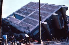
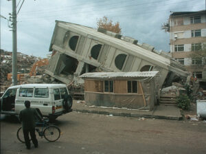
Damage of earthquake depends upon many factors like intensity, duration & frequency content of the ground motion, geologic and soil condition, quality of construction, etc. some sociologic factors are also important, such as time of the day of the earthquake occurrence, density of population.


Importance of Earthquake Study
Earthquakes have been the cause of great disasters in the form of destruction of property and injury and loss of life. Earthquake is the only hazard in which loss of life is done due to man-made structures so properly designed buildings can prevent loss. So it is necessary to know the type of earthquake and to construct earthquake resisting buildings it is also necessary. It is necessary to know that the building, which is constructed, is in which zone. The zone is an area in which an earthquake of some particular value of intensity and frequency occurs. The zone is depends upon the frequency and intensity of the earthquake. In Indian, as per IS code, there are 5 zones.
Need of a Good Design Concept
Sometimes it happens that the building does not collapse in a major earthquake is a collapse in after-shock. So it is necessary that the building be well designed with proper detailing. A significant characteristic of a good design concept is the idea of ductility. Proper detailing is as important as the need for a good design concept, in which detailing members and their connections to achieve the requisite strength and ductility. The aim of such detailing is to prevent non-ductile failure.
Experience and observation both have shown that correctly designed, detailed, and constructed reinforced concrete building structures can provide the required strength, stiffness, and inelastic deformation capacity to perform satisfactorily under severe earthquake loading.
Object and Scope
The following are the objectives of earthquake-resistant design and detailing of structures.
- To have an idea about the general principles of earthquake-resistant construction.
- To appreciate the need for earthquake-resistant design and detailing.
- To study factors controlling damage during an earthquake.
- To understand minor cares required in earthquake-resistant construction.
- To examine the essence of ductile detailing.
- To know the basic codal provisions of the ductile detailing.
Factors Affecting Damage
Building Configuration
The building configuration means the shape, size, and proportions of the three-dimensional form of the building. In addition to this, the configuration includes the location, shape, and approximate size of the major structural elements. An important feature is a regularity and symmetry in the overall shape of a building. The regular configuration is optimum or ideal with respect to detailing with lateral forces. A building shaped like a box, such as rectangular both in elevation and plan, is inherently stronger than that is U-shaped or L-shaped, such as a building with wings. An irregularly shaped building will twist as it takes shakes, increasing the damage of the building.
In short, the structure that is symmetrically ideal has the following characteristics.
- Low height-to-base ratio
- Balanced resistance
- Symmetrical plan
- Uniform section and elevation
- Maximum torsional resistance
- Short span
If the height-to-width ratio is more the tendency to overturn is increased while low height-to-width ratio minimizes the tendency to overturn. Equal floor height provides equal column/wall stiffness. Due to the symmetrical plan shape, it reduces torsion while an unsymmetrical plan increased torsion. Therefore it is desirable to restrict the length of a block to three times its width uniform section and elevation eliminates stress concentrations.
Construction Quality
In many cases, the failure of buildings in an earthquake has been attributed to poor quality of construction, substandard materials, poor workmanship, e.g. inadequate skill in bonding, absence of “through stones” or bonding units, and inadequate and improper construction.
The following are the main weakness in the unreinforced masonry constructions and materials and other reasons for the extensive damage of such buildings.
- Heavyweight and very stiff buildings, attracting large seismic inertia forces.
- Low tensile strength, particularly with poor mortars.
- Brittle behavior in compression as well as tension
- The weak connection between wall and wall.
- The weak connection between roof and wall.
- Stress concentrations at corners of windows and doors.
- Overall un-symmetry in plan & elevation of the building.
- Defects in construction such as the use of sub-standard materials, unfilled joints between bricks, not-plumb walls, improper bonding between walls at right angles, etc.
Foundations
Buildings, which are structurally strong to withstand earthquakes sometimes, fail due to inadequate design of the foundation. Cracking, tilting, and failure of superstructures may result from soil liquefaction and differential settlement of footing. Certain types of foundations are more susceptible to damage than other foundations. For example, isolated footings of columns are likely to be subjected to differential settlement particularly where the supporting ground consists of different or soft type’s soil. Mixed types of foundations within the same building may also lead to damage because of differential settlement.
Small Things to Be Remember
General
The study of the minor cares in the design & construction can be best studied under the following five heads.
In Design of Footing
- Leveled foundation bed (provision of BBCC under footing).
- Provision of tie beams at the foundation level if the soil is loose or at plinth levels.
- Provision of start-up bars of sufficient length.
- Column ties shall start from the base of the footing.
- Sufficient cover to the reinforcements (as they will be normally inaccessible after the construction).
- The suitable factor of safety in the bearing capacity of the soil.
In Design of Column
- Earthquake force is acting in all directions, so it is preferable to use a square section of columns other than rectangular.
- Vertical reinforcement should be distributed on all faces of columns. The use of 8 vertical bars is preferable than the use of 4 bars of the same area. The minimum diameter of the bar is 12 mm.
- Concrete confined within the spiral is stronger as well as much more ductile as compared with plain concrete or that containing widely spaced stirrups.
- The behavior of columns can be much improved by using the ties with an adequate anchorage at the ends in the form of suitable hooks.
- In a length of about 450 mm near the ends of columns, a spacing not more than 100 mm may be adopted for achieving ductility.
- The corner columns of buildings are stressed more than any other column of buildings due to biaxial bending and must, therefore, have steel distributed on all faces and closely spaced lateral ties.
In Design of Slab
- Sufficient cover to the bottom reinforcements, especially at the center of the span, having concealed wiring.
- Continuous concreting.
- Sufficient reinforcements over the continuous supports.
- Provision of additional reinforcements around the openings in the slab.
In Design of Beam
- Beams should be reinforced on both top and bottom faces throughout. Where reinforcement is required by calculation, the percentage should correspond to ductile behavior. The recommended limits on the steel area are the following.
- Minimum steel should consist of 2 bars of 12 mm diameter in case of mild steel and 2 bars of 10 mm diameter in case of high strength deformed bars.
- All longitudinal bars should be anchored/spliced for full strength development. All spliced should be contained within at least two stirrups at each end of the splice so as to avoid spalling of cover concrete.
- The ultimate shear strength of the beam should be designed to be more than its ultimate flexural strength. Vertical shear stirrups should be closely spaced at not more than 1/4 of effective depth in end 2h-length of spans of the beams. In the remaining length, the spacing of the beam should not exceed h/2.
Connection
- The column and beam bars must be well anchored in the compression zone so as to achieve their full strength.
- Where beams on all 4 sides do not confine the joint, it will be necessary to place the closely spaced ties in the column throughout the height of the joint as well.
- The monolithic construction of the connections.
In Design of Wall
- A freestanding wall must be designed to be safe as a vertical cantilever.
- Horizontal reinforcement in walls is required for transferring their own out-of-plane inertia load horizontally to the shear walls.
- The walls must be effectively fixed together to avoid separation at vertical joints due to ground shaking.
- Shear walls must be present along both axes of the buildings.
- A shear wall must be capable of resisting all horizontal forces due o its own mass and those transmitted to it.
Ductility and Building
Ductility
Ductility can be explained as the “ability of the material to undergo large deformations without rupture before failure.”
Ductility in concrete is explained by the percentage of steel reinforcement within it. Mild steel is an example of a ductile material that can be twisted and bent without rupture. Member ductility or structural ductility is also defined as the ratio of absolute maximum deformation to the corresponding yield. This can be defined with respect to strains, rotations, curvature, or deflections. Strain based ductility definition depends on the material; while curvature-based or rotation ductility definition also includes the effect of shape and size of the cross-sections.
Significance of Ductility
- If ductile members are used to forming a structure, the structure can undergo large deformations before failure. This is advantageous to the users of the structures, as in case of overloading if the structure is to collapse; it will undergo large deformations before failure and thus provides a warning to the occupants. This gives notice to the occupants and provides sufficient time for taking preventive measures. This will reduce the loss of life.
- Structures are subjected to unexpected overloads, load reversals due to foundation settlement and volume changes. These items are generally ignored in the ductile than taken care of by the presence of some ductility in the structure.
- The limit state design procedure assumes that all the critical sections in the structure will reach their maximum capacities at the design load for the structure. For this to occur, all joints and splice must be able to withstand forces and deformations corresponding to the yielding of the reinforcement.
Necessity of Ductile Detailing
Ductile detailing is provided in structures so as to give them adequate toughness & ductility to resist severe earthquake shocks without collapse.
Ductile detailing is provided for the following structures.
- The structures are located in seismic zone IV and V.
- The structure is located in seismic zone III and has an important factor greater than 1.
- The structure is located in seismic zone III & is an industrial structure.
- The structure is located in seismic zone III & is more than 5 stories high.
Ductility Criteria for Earthquake Resistant Structures
The performance criteria in most earthquake code provisions require that a structure be able to as below:
- Resist earthquakes of minor intensity without damage. A structure would be expected to resist such frequent but minor shocks within its elastic range o stresses.
- Resist moderate earthquakes with minor structural & some non-structural damage. With proper design and proper construction, it is believed that structural damage due to the majority of earthquakes will be limited to repairable damage.
- Resist major catastrophic earthquake without collapse.
Designs for Ductility
Following certain simple design details such as can ensure a sufficient amount of ductility:
- The structural layout should be regular and simple avoiding offsets of beams to columns, or offsets of columns from floor to floor. Changes in stiffness should be gradual from floor to floor.
- The amount of tensile reinforcement in the beam should be restricted and more compression reinforcement should be enclosed by stirrups to prevent it from buckling.
- Beams and columns in a reinforced concrete frame should be designed in such a manner that inelasticity is confined should remain elastic. To ensure this, some of the moment capacities of the columns for the design axial loads at a beam-column joint should be greater than the moment capacities of the beams along each principal plane.
- Closed stirrups or spirals should be used to confine the concrete at sections of the maximum moment to increase the ductility of the member. Such sections include lower and upper ends of columns and within beam-column joints, which do not have beams on all sides. If the axial load exceeds 0.4 times the balanced axial load, a spiral column is preferred.
- Splices and bar anchorages must be sufficient to prevent bond failures.
- The reversal of stresses in columns and beams due to the reversal of the direction of the earthquake force must be taken into account in the design by appropriate reinforcement.
- Beam-column connections should be made monolithic.
Ductile Detailing for Flexure Member
- The factored axial stress on the member under earthquake loading shall not be greater 0.1fck.
- The member shall have preferably had a width-to-depth ratio of greater than 0.3.
- The width of the member shall not be less than 200 millimeters.
- The depth of the member shall preferably be not lower than ¼ of the clear span.
- In an external joint, both the bottom and top bars of the beam shall be provided with anchorage length, beyond the inner face of the column, equal to the development length in tension plus (+) 10 times the bar diameter minus (-) the allowance for a 90-degree bend.
- In an internal joint, both face bars of the beam shall be taken without interruption through the column.
Purpose
Flexure members of lateral force resisting ductile frames are supposed to yield at the design earthquake load. To ensure proper development of reversible plastic hinges near-continuous supports where they are usually developed in such members.
Lap, Splice in Beam
The longitudinal bars shall be spliced, only if hoops are provided over the entire splice length, at a spacing not exceeding 150 millimeters.
Purpose
For confining the concrete and to support longitudinal bars,
- Intension, the lap length shall not be less than the bar development length.
- Lap splices shall not be provided
- Within a joint
- Within a quarter length of the member where flexural yielding may generally occur under the impact of earthquake forces.
- Lap, splice in beam within a distance of 2d from the joint face.
- Not more than 50% of the bars shall be spliced in one section.
Purpose
To avoid the probability of spalling of concrete cover under large reversed strains.
Beam Reinforcement
The spacing of hoops over a length of 2d at either end of a beam shall not exceed as below
- d/4
- 8 times the diameter of the smallest longitudinal bar
- The first hoop shall be at a distance not exceeding 50 millimeters form the joint face.
- Vertical hoops reinforcements at the same spacing shall also be provided over a length equal to 2d on either side of a section where flexural yielding may occur under the impact of earthquake forces.
- Elsewhere, the beam shall have vertical hoops at a spacing not more than d/2.
Column and Joint Detailing
- Lap splice shall be provided only in the central half of the length of the member. It should be proportioned as a tension splice. Hoops shall be provided over the entire splice length at a spacing not exceeding 150 mm center to center. Not more than 50% of the bars shall be spliced in one section.
- The spacing of the hoops shall not be more than half the least lateral dimension of the column, except where special confining reinforcement is provided.
- The larger lateral dimension of the member at the section where yielding may occur.
- One-sixth (1/6) of the clear span of the member.
- The special confining reinforcement as required at the end of the column shall be provided through the joint.
- A joint, which has beams framing into all vertical faces of it & where each width of the beam is at least ¾ of the width of the column, may be provided with half the special confining reinforcement required at the column end. The spacing of the hoops shall not be more than 150 millimeters.
- When a column terminates into a mat or footing, special confining reinforcement shall extend at least 300 millimeters into the footing or mat.

