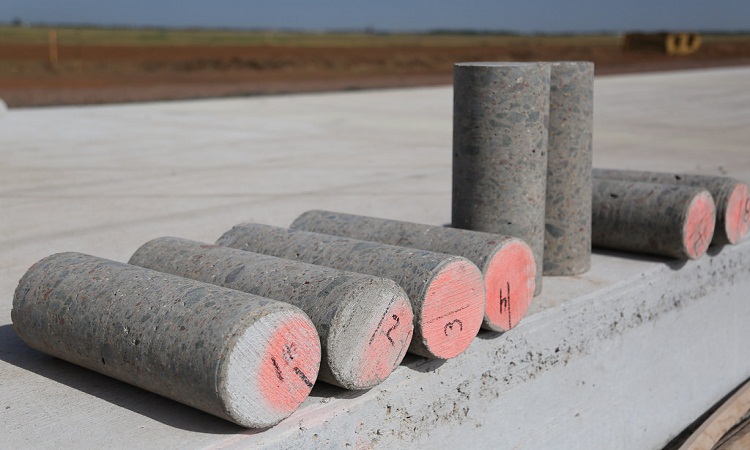
Concrete cores are used for testing actual properties of concrete in existing structures such as strength, chemical analysis, permeability, carbonation, etc. The concrete core sample and concrete core test describes the strength of concrete.
While non-destructive test Surface hardness test, Rebound hammer test, Dynamic or Vibration test, Radioactive and nuclear method methods, Ultra pulse velocity test give indirect evidence of concrete quality, a more direct assessment on strength can be made by concrete core test.
Technical Checklist for Concrete Core Testing
- Take core samples after the concrete is strong enough to permit sample removal without disturbing the bond between the mortar and coarse aggregate. Cut surfaces should not display the exposed coarse aggregate particles and erosion of the mortar should be firmly embedded in the mortar. Don’t use samples that have been damaged during removal.
- Locate reinforcement and drill cores so they don’t contain any embedded reinforcement.
- Drill concrete cores perpendicular to the surface and not near formed joints or obvious edges of concrete placement.
- Take cores near the middle of a concrete placement when possible. In walls or columns, for instance, samples should be taken near mid-height, not at the top or bottom.
- The diameter of the core specimens must be at least three times the nominal maximum size of coarse aggregate. The preferred length of the capped or ground specimen is between 1.9 to 2.1 times the diameters. However, ASTM C 42 provides correction factors for tests on cores with length to diameter ration between 1 and 2.
- After the cores have been drilled, wipe drilling water off the surface & allow the remaining surface moisture to evaporate.
- When surfaces of the core appear dry, but not later than 1 hr after drilling, place cores in separate plastic bags or non-absorbent containers and seal the bags to prevent moisture loss.
- Transport cores to the testing lab as soon as possible.
- Keep cores in the sealed plastic bags or non-absorbent containers at all times except during end preparation. Leave in laboratory air for no more than 2 hours to permit capping before testing.
- If water is used during the sawing of core ends, complete this operation as soon as possible, but no later than 2 days after drilling of cores. After completing end preparation, wipe-off surface moisture, allow the surfaces to dry and place the cores in non-absorbent containers or sealed plastic bags.
- Allow the cores to remain in the non-absorbent containers or sealed plastic bags for at least 5 days after last being wetted and before testing.
- Saw the ends, when necessary, as per with requirements in ASTM C 39.
- Cap the ends, when necessary, as per with requirements in ASTM C 617.
- Before testing, measure the length of the capped or ground specimen to the nearest 0.1 inches and use it to compute the length-to-diameter ratio.
- Determine the average diameter of the core by averaging two measurements taken at right angles to each other at the mid-height of the specimen. Measure core diameters to the nearest 0.2 mm when the difference in core diameter doesn’t exceed 2% of their average, otherwise measure to the nearest 2 mm. Do not test core if the difference between the largest and smallest diameter exceeds 5% of the average diameter.
- Test specimen at 7 days after coring.
- Test core in accordance with the requirement in ASTM C 39.
- Report core test results as per ASTM C 42 requirements.
Factor Affecting the Compressive Strength of Concrete Core Test
The factor that are significant which influence the compressive strength of core are :
- Moisture and Voids
- Length/Diameter ratio of core
- Diameter of core
- Position of cut out concrete in the structure
- Direction of drilling
- Effect of age
Moisture and Voids:
The moisture condition of the core influences the measured strength. It has observed that a saturated specimen has a value of 10% to 15% lower than comparable dry specimens. Thus while estimating the actual in-situ concrete strength the relative moisture conditions of the core and the in-situ concrete should be taken into consideration.
Voids in the core concrete will reduce the measured strength. Peterson found that the ratio of core strength to standard cylinder strength at the same age is always less than 1.0 and decreases with the increase in the strength of the cylinder. Up to cylinder strength of 20 MPa it is just less than 1 and 0.7 for 60 MPa strength.
Length/Diameter Ratio of Core:
It has been observed that as the L/D ratio increases, the measured strength decreases due to the effect of specimen shape and stress distribution during the test. For establishing a relationship between core strength and standard cube strength, the ratio of L/D = 2.0 is taken as the basis of computation.
Diameter of Core:
The diameter of the core may influence the measured strength and variability. Measured concrete strength decreases with the increase in the size of the specimen. This effect is significant. However, this effect will be small for size above 100 mm, but for smaller size this effect is significant.
Position of cut out concrete in structure:
Cores taken from near the top surface have usually the lowest strength may it are a column, beam, wall, or slab. With the increase in depth below the top surface the strength increases but at depths more than 300 mm, there is no further increase in strength. The difference maybe 10% to 20%. In the case of slabs, poor concreting increases this difference.
Direction of Drilling:
Due to the layering effect, the measured strength of the specimen drilled vertically relative to the direction of casting is likely to be greater than that for a horizontally drilled specimen from the same concrete.
Effect of Age:
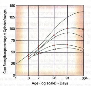
It has been observed that in-situ, concrete gains little strength after 28 days. Tests on high strength concrete have shown that through the core strength increases with age up to 1 year, but remain lower than the 28 days standard cylinder strength as shown in the figure. On the other hand, Petersons have suggested the increase in core strength over that of 28 days cylinder strength as 10% after 3 months and 15% after 6 months. Thus the effect of age is not easy to discuss, but in the absence of definite moist curing, no increase in strength should be expected.
Effect of End Condition of the Core
When the core is tested in compression, the top surface of the core is brought into contact with the platen of the testing machine. If the top surface is apparent somewhat rough and not truly plane, stress concentration is introduced hence resulting in a reduction strength of concrete.
The end of the specimen that is not plane within 0.05 mm. are to be capped. To avoid this loss of strength, the end surface should essentially be made the plane. The ill-effects of the uneven end surface of the core can be eliminated to a great extent by either capping the core with suitable material or grinding. Test specimens may be capped with a thin layer of stiff Portland cement paste or mortar of stiff consistency using cement similar to that used in the concrete and sand which passes IS sieve 300 but retained in IS sieve 150 or sulfur mixture consisting of 1 part of sulfur to 2 or 3 parts o inert filler such as fire clay or hard plaster having a compressive strength of at least 420 Kg/cm2. The following are essential for all capping materials:
- The cap should be thin and care should be taken to ensure that flaws or fractures do not take place in the cap itself when the specimen is tested.
- The capping material must neither be weaker than the concrete in the core nor very much stronger than the concrete in the core.
- The planeness of the cap must be checked by means of a straight edge and a feeler gauge, taking at least three measurements on different diameters.
Effect of the Height/Diameter ratio (H/D ratio) on Strength
Readers are that standard cylinder test specimens are of height “h” equal to twice the diameter “d”. in the case of cores cut from in-situ concrete, the diameter of the core depends on the diamond-studded cutting tool. The height of the core will depend on the thickness of the concrete member.
If the core is too long, it can be trimmed to the h/d ratio of 2 before testing the core. However, if the length of the core is too short, it is necessary to estimate the strength of the same concrete as if it had been determined on a specimen with h/d equal to 2.
Correction Factor
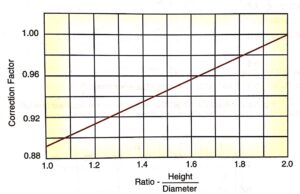
It is necessary to apply a correction factor whenever there is a deviation in the diameter or height of the core and/or when the h/d ratio does not equal 2.0. Different correction factors as given below can be used.
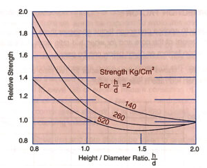
- The figure shows the correction factor for the h/d ratio of the core (IS 516-1959) when the h/d ratio is less than 2.0.
- Murdock and Kesler found that the correction factor is not a constant one but depends on the strength level of the concrete. High-strength concrete is less affected than low-strength concrete. The figure shows three curves representing different strengths that display relative strengths for different h/d ratios.
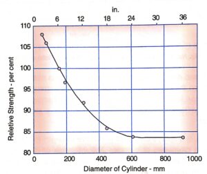
- The figure displays the effect of the relative strength of concrete on various diameters of the cylinder. The influence of diameter disappears beyond a certain size. Any further increase in the size of a member does not lead to a decrease in strength. However, for smaller diameters, the strength variation is most pronounced and should not be ignored.
- Cores with h/d ratio lower than 1.0 yield unreliable result; BS 1881 Part 4, 1970 specifies a minimum value of h/d 0.95. This limitation must be observed. Gluing o cores that are too short is possible. The above standard specifies the use of 100 mm or 150 mm cores. However, cores as small as 50 mm have been successfully used in Switzerland and are permitted in German and Swiss standards.
- Very small cores exhibit more variations than the larger ones. Their use is thus normally not recommended. The core diameter should not be less than 3 times the maximum size of aggregates (MAS). An increased number of cores may have to be tested to arrive at the average potential strength of the core in such cases.
- The general pattern of influence of the h/d ratio on the apparent strength of the cylinder can be seen in the figure.
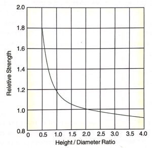
For the value of h/d smaller than 1.5, the measured strength increases rapidly owing to the restraining effect of platens of the testing machine. When h/d varies between 1.5 to 4.0 the strength reduction is very little. For h/d values between 1.5 to 2.5, strength is within 5 percent of standard specimen h/d = 2. From this figure, it is apparent that the choice of standard h/d ratio of 2 is suitable because a slight departure from this ration does not seriously affect the measured value of strength. If the core is too short, it is necessary to estimate the strength of the same concrete as if it had been determined. Such a situation may arise when cores have to be taken from road pavements, airfield pavements, roof slabs, and foundation concrete.
Action to Be Taken When the Core Test Fails to provide Structural Adequacy
If the structural adequacy remains in doubt, the accepting authority may require carrying out load tests, particularly in the case of floor or roof systems. On the other hand, if time and conditions permit, a sincere effort may be made to improve the strength of concrete in place by supplemental wet curing for some time. It is necessary to verify the effectiveness of such treatment by conducting strength evaluation tests once again before giving acceptance.
