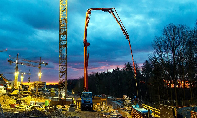
Pumped concrete is the concrete that is transported to heights by means of pumping using concrete pumps. Pumped concrete is utilized where a large quantity of concrete work is involved at a greater height, where different methods of transport are not easy to do.
Concrete pumps have been known for more than fifty years. In the current scenario, large quantities of concrete can be transported by means of pumping through pipelines over considerable distances, often to construction sites that may not be easily accessible by other means of delivery.
The method for pumping concrete consists of a hopper into which the concrete is discharged from the mixer, which in turn, feeds the concrete pump itself and finally the delivery pipelines through which the concrete is delivered.
Concrete Pumps and Pumping Capacity
Generally, concrete pumps are either mounted on a truck or on a trailer. The pumps are either diesel or electrically operated. The concrete is pumped through the pipeline of diameter between 100mm to 180mm. The most popular and suitable diameter for normal pumping is 125mm.
Modern portable concrete pumps now manufactured in overseas countries are in their fifth generation having enormous power, high capacity, and absolutely reliable hydraulic system. They can pump concrete to a height of nearly 500M or cover a horizontal distance up to 2000M. The pumps have a hydraulic system that can concrete pressures up to 200 bars. The pump’s outputs range from 19m3 to 150m3 per hour. Different manufacturers have developed different types of valves or systems. The rock valve, ‘C’ valve system, flat gate valve, and ‘S’ trunk system are generally adopted depending on the customer’s choice, and use or the manufacturer’s patented system.
However, it may be noted that the rock valve system got its name in Germany. In the German language, rock means a woman’s skirt and since the valve has a similar shape and movement it is called so.
Concrete pumps are generally designed with adequate protection against adverse usage, they are insensitive to rough treatment and operation on construction sites, have a sturdy construction, and are easy to maintain.
The gate valve cut through concrete and fully lined with highly wear-resistant metal and can be quickly replaced if it is worn out. Rams are of special vulcanized rubber, lined with steel core, and are easy to replace as they have quick detachable connectors. The metal core is fully encased to avoid concrete adhesion.
Control systems of all concrete pumps are fully hydraulic, compact, and dirt sensitive. The hydraulic pump is output-regulated and therefore, optimizes motor-power utilization at ideal pressure and speed. The instrument panel is well arranged and indicates pressure in the system and has necessary operating controls.
The outlet section of the pump is made up of a taper and a clamping device for connecting to the pipeline. It is quick and easy to clean and has a simple side swing. The agitator helps maintain the concrete in an agitated form between two batches of concrete fed into the hopper. The high-torque drive ensures constant rotation even with stiff and rough mixes.
The concrete pump conveying unit is mounted on a truck chassis. The drive of the hydraulic pump is directly driven from the truck engine. A hydraulically-driven water pump is fitted to the water tank. This pump is used for evacuation of conveying pipeline with pressured water and for cleaning the concrete pump. The swivel pipe system evolved by Rock Chieber is generally found on the truck-mounted pump in place of the gate-valve system.
The outstanding characteristic of this swivel pipe system is the perfect and absolute balancing of movements under any condition. This makes the shaft and bearing free from wear. The swivel pipe system improves pumpability even on longer distances and higher vertical reaches because they are less cost-effective than flat gate valve systems on high-rise building sites. However, the flat valves are favorably used when poor, harsh, or oversized aggregate concrete to be pumped.
Concrete pump manufacturers usually list a maximum theoretical output or pump capacity in cubic meters per hour, which depends on the distance to which it can pump, the line size, and the maximum line pressure.
Output of Pump for Pumped Concrete
The concrete pump output depends on several factors such as:
- Length of horizontal pipe.
- Length of vertical pipe.
- A number of bends especially shaped bends.
- Diameter of the delivery pipeline.
- Length of the flexible hose.
- Changes in line diameter or reducers.
- Workability of concrete measured as a slump.
- The cohesiveness of the concrete.
- Type of aggregates used in the concrete.
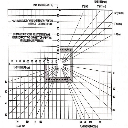
The below figure shows line pressure and pumping rates as functions of line diameter, pumping distance, and slump. Once the desired pumping rate is known, line diameter can be finalized along with pumping distance and slump, and the likely line pressure can be conveniently worked out. For example, if the desired pumping rate is 25m3/hr, the line diameter, pumping distance, and slump are finalized as 125mm, 300m, and 80mm, respectively. Therefore, the line pressure works out to 36.40 bars.

In actual practice the pump will seldom be in operation continuously.
Calculation of pressure in a concrete pipe line can be estimated using the following guidelines.
| Start up pressure required by pump | 20.0 bars |
| Every 20m horizontal pipeline | 1.0 bar |
| Every 4m vertical pipeline | 1.0 bar |
| Every 90o elbow | 1.0 bar |
| Every 45o elbow | 0.5 bar |
| Every pipe coupling | 0.1 bar |
| Every 5m of end hose (flexible) | 2.0 bars |
| Safety factor | 10% of total |
If a trailer pump is installed 40m away from the building and is required to pump concrete 100m vertically the calculations of pressure are as given below:
| Start up pressure | 20 bars |
| Vertical delivery line (100m)/(4) | 25 bars |
| Horizontal delivery line (40m)/(20) | 2 bars |
| Couplings (60 Nos)/(0.1) | 6 bars |
| Elbow 90o (2 Nos)x(1) | 2 bars |
| End hose 5m (1 No)x(2) | 2 bars |
| Total | 57 bars |
| Add 10% for safety factor | 6 bars |
| Total Pressure | 63 bars |
If a truck-mounted placer boom and pump unit with a vertical/horizontal reach of 36/33m is required to place concrete at about 18m height, the pressure calculations are as given below:
| Start up pressure | 20.0 bars |
| Vertical delivery line (20m)/(4) | 5.0 bars |
| Horizontal delivery line (36-20)/(20) | 0.8 bars |
| Elbows (6 Nos)/(1) | 6.0 bars |
| Coupling (12Nos)/0.1 | 1.2 bars |
| End hose 5m (1 No)x(2) | 2.0 bars |
| Total | 35.0 bars |
| Add 10% for safety factor | 3.5 bars |
| Total Pressure | 38.5 bars |
It must be noted that maximum pressures indicated in the leaflets and manuals cannot be exploited as the pre-controlled safety valves start opening at 90% of the set pressure.
For all hydrostatically driven pumps it is obligatory that working pressure does not exceed 90% of the pressure indicated by the manufacture, i.e. set pressure. In addition to the above, line size, job layout, concrete properties and pump output derived on the basis of estimated downtime are taken into account in calculating the required pumping pressure.
The combination of the output and required pumping pressures can be used to choose the best pump for the job.
It should be borne in mind that unless the site has proper infrastructure to produce concrete of consistent and good quality with good speed, attempts should not be made to do the pumping, as it will lead to disastrous results.
Concrete production and transportation to the pump play an important role in pumping concrete. If placing boom is not available, handling of flexible hose and other pipelines could become a major constraint in the downtime calculation.
Compaction of concrete must have adequate speed to cope with the placing rate. Formwork design needs careful examination as hydrostatic pressure due to rapid build-up of concrete in formwork would be much larger than in the case of conventional manual placing of concrete.
The reinforcement layout also needs to be modified to allow for the lowering of the flexible hose closet to the placing point. To start, 30m3/hr to 40m3/hr capacity would be adequate, provided the above points are properly taken care of. Besides the selection of concrete pump and pipeline, equipment such as truck/mounted mixer, automatic/manually-controlled batching plant, and placing boom plays a very important role in successful concrete pumping operation.
Concrete is mostly fed to the concrete pump hopper using the truck-mounted mixer. It is to be noted that a proper selection of the combination of various equipment can greatly influence the quality, speed, and economy of concrete.
Advantages of Pumped Concrete
One of the main advantages of pumped concrete is that concrete can be moved both horizontally and vertically in one go. The pump output normally varies from 30m3 to 150m3 of concrete per hour.
A concrete pump is one of the greatest aids to quality control. It is the most sensitive method in which any variation in mix consistency or workability can be easily detected at the pumping point by observing the pumping pressures. It acts as silent quality control equipment, refusing to handle any concrete which is unduly harsh, inadequately mixed, non-cohesive, and not correct n consistently.
In India, it is no longer easy to mobilize large gangs of labor at frequent intervals for concreting and, therefore, for large concrete pours it would be beneficial to use concrete pumps to do concreting at a much faster rate.
Pumped concrete normally good cohesion and high workability and thus, gives a better finish and strength to concrete structures. Concrete can be placed in inaccessible areas very easily. Mass concreting can be carried out in a limited time and at high speed, without cold joints.
Using concrete pumps can help speedier completion of contracts and thereby, help in improved cash flow, reduction in site-overheads, and better utilization of resources.
Pipeline for delivery of the concrete occupies very little space and can be easily extended or removed.
Delivery of concrete is in a continuous stream. If the mobile-boom pump is used, both vertical and horizontal movements for placing concrete are possible, thereby eliminating the need for drop chutes and elephant trunks. Concrete should be placed closer to its final position in form reducing shoveling/dragging of concrete thereby avoiding segregation of the concrete mix.
Disadvantages of Pumped Concrete
The conveying capacity of concrete pumps is limited, so the conveying distance and height of concrete are limited. Pumped concrete is not suitable when the distance is too far and the vertical height is too large.
Pumped concrete requires the pumpability of the concrete to be transported, which will increase the water-cement ratio of the concrete. Such concrete is prone to cracks and shrinkage.
The concrete slump used by the concrete pump for pumping concrete construction is relatively large, and the pouring speed is very fast. Pumping concrete causes the concrete pressure measurement to become larger, so the utilization of pumped concrete has higher structural requirements for the formwork.
Pipeline for Pumped Concrete
The pipeline supplying concrete is made from seamless pipes of high-quality precision steel and consists of straight sections and bends which are connected by means of detachable couplings. The inside diameter of pipelines generally used varies from 80mm to 180mm and length from 0.5m to 3m. In addition to 90o bends, 15o, 30o, 45o, and 60o bends are also available. The choice of the diameter of the pipeline depends on the following factors.
- Size and type of concrete pump.
- Required horizontal and vertical placement distances.
- Quality of concrete to be pumped with regard to its consistency.
- Maximum size of aggregates.
The total effect of bends, vertical rise, and flexible hoses on a laid pipeline is calculated in terms of horizontal pipe length. This correlation for over 100mm internal diameter pipeline is as follows:
1m vertical rise = 2m to 3m horizontal length
One 90o bend = 3m horizontal length
One 45o bend = 2m horizontal length
One 30o bend = 1m horizontal length
1m rubber pipe = 2m steel pipe
For Indian conditions, a 125mm diameter pipe is the most suitable. However, over 150mm diameter pipe is not advisable under any circumstances. Pipes of various thicknesses are available with thickness varying from 4mm to 7mm. For tough pumping jobs such as high-rise buildings, 7mm thick pipes are recommended, whereas for normal pumping jobs not involving huge vertical lifts or very stiff concrete, 5mm thick pipes are suitable.
Normally, at the end of each delivery line, a flexible hose is kept for facilitating placement and handling. However, over 5m length of flexible hose is not desirable. Flexible hose with 2 to 4 layers of high tensile steel cable reinforcement are available and can withstand pressures up to 50 bars. The tube rubber is smooth and abrasion-resistant.


